How to flash an ATtiny 25, 45 or 85 with Arduino
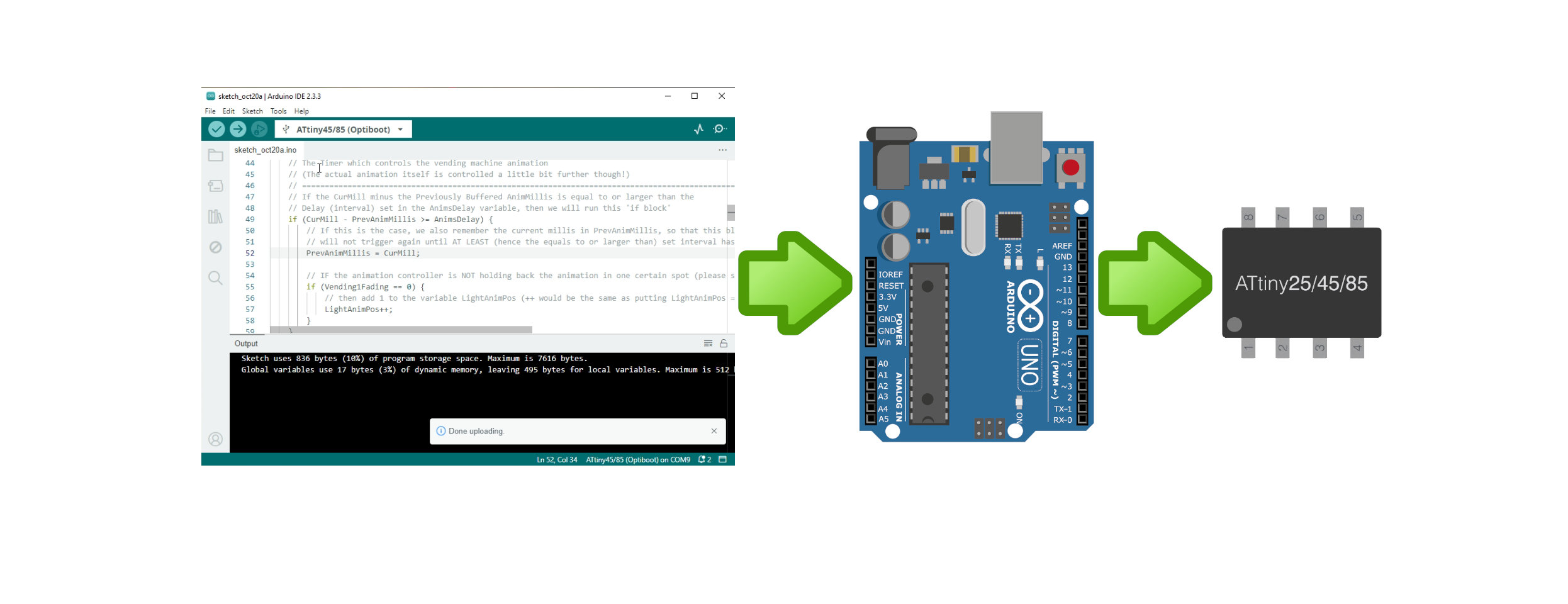
In this article I will try to keep it as simple as possible (in terminology) but also as complete as possible about what the ATtiny microcontrollers are, what they can do and how to flash them with something like your standard Arduino UNO (or clone) board.
What is the ATtiny?
Well to keep it very simple and short: The ATtiny series are (much) smaller microcontrollers than the most commonly used ATMega328 for example (the same one which goes into the Arduino UNO), not only in (physical) size, but also in storage size (ROM). I’m pretty sure we all had our projects where we would for example only need one or two pins, but did actually needed ‘programmed code‘ to perform a specific task. Would this then mean that we would have to waste an entire ATmega328 for just two pins and for example 500 bytes of code? Nope, that’s where the ATtiny’s come in. They are smaller, have less pins, less storage, less ram, often have a lower power consumption, (often) need less external components and are cheaper. So all in all: A much better solution than wasting an entire ATmega328 on a Tiny project (pun intended)😉.
ATtiny25/45/85 Pinout
Below you will find the full ‘technical’ pinout of the ATtiny25, 45 and 85 when using the MCU Core which I would recommend using (explained further on).

While this pinout is great for those who know what timers are, and for example want to know on which pins which timer is ‘connected’ etc (let’s just say ‘the more advanced user’), it can be a bit overwhelming for beginners. Therefor I have also created a more simpler ‘Arduino Pins’ pinout below.

Differences between ATtiny25, ATtiny45 and ATtiny85
The main differences between these 3 ‘models’ are the Flash (program) size, the EEPROM (which can be used for ‘storing settings’ for example) and SRAM (Memory/RAM).
| Microcontroller | Flash (Program Memory) | SRAM (Memory / RAM) | EEPROM (‘Settings Storage) |
|---|---|---|---|
| ATtiny25 | 2KB | 128 Bytes | 128 Bytes |
| ATtiny45 | 4KB | 256 Bytes | 256 Bytes |
| ATtiny85 | 8KB | 512 Bytes | 512 Bytes |
If you want to see all the technical details of these ATtiny Microcontrollers then I would recommend looking at the Datasheet. Personally I recommend to always keep a copy of each datasheet of the IC’s and microcontrollers you use locally on your computer or network.
Maximum Currents, Resolution and Limits (short summary)
NOTE: Please make sure to consult the datasheet for accurate and full details in regards to all the technical data of your microcontroller! This section if only intended to give a quick and short overview/reference and some basic tips from my point of view.
Architecture: 8-Bit CMOS based on the AVR enhanced RISC architecture
MCU Speed: 0-10MHz at 2.7 to 5.5 Volts and 0-20MHz at 4.5 to 5.5 Volts
Operating Voltage: 2.7 – 5.5 Volts
Operating Temperatures: from -40°C up to +85°C
GPIO (General Purpose I/O) Pins: 6, but I recommend to use 5 at maximum (and not to use the reset pin as I/O!)
ADC Resolution (analogRead): 10 Bit ADC (values from 0 to 1023)
EEPROM Lifespan: 100.000 Write/erase cycles (per bit), NOTE: Reading doesn’t affect the EEPROM lifecycle!
ROM Lifespan: 10.000 Write/erase cycles
Data Lifespan (retention): 20 years at 85°C or even 100 years at 25°C
Recommended Max Current per pin (sink or source): 5mA
Absolute Maximum Current per (I/O) pin: 40mA*
Absolute Maximum current whole package: 200mA*
* Please note that these absolute maximum ratings should never be exceeded, doing so will permanently damage your microcontroller. The whole package maximum basically means that all the pins together should not exceed sourcing or sinking 200mA all together. So this would mean that if you for example have a microcontroller with 40 pins and 15 pins of that microcontroller would be sourcing 20mA each, that you are sourcing a total of 300mA. If your ‘whole package maximum’ would then for example be 200mA, then you would be pushing the microcontroller (way) over it’s maximum limit, even if you are below the current limit per I/O pin.
Special Notes:
The Reset pin (pin 1) can also be used as a (weak!) I/O pin, I however don’t recommend doing this if you don’t exactly know what you’re doing because doing this incorrectly could cause unexpected behavior like for example ‘sudden’ resets. As you will see in the Minimal (Recommended) pinout below, I would actually recommend using a 10K pull-up resistor on the reset pin instead for most users.
Minimal (Recommended) Pinout
Below you’ll find the minimal circuit needed to operate the ATtiny25, 45 and 85 (without any of your own components added to it that is, and without a programmer connected). This is basically the circuit which you should start ‘building on’ when doing a project with these microcontrollers.

The 100nf capacitor is usually not mentioned in the minimal circuit for the this microcontroller, but I do strongly recommend using it for (greatly) improved stability. Same goes for the 10K pull-up resistor from the reset pin (pin 1) to VCC, this one is officially also not needed because the ATtiny25/45/85 does has an internal pull-up resistor, but using an (stronger) external one of 10K can reduce the risk of your microcontroller unexpectedly rebooting due to external interference significantly.
Flashing (Uploading sketches/firmware to) the ATtiny
By default the ATtiny series aren’t supported by the Arduino IDE, and of course you can’t just shove that tiny😉 8-pin microcontroller into the slot of your Arduino UNO either. So we will need to install some additional (core) libraries, and also ‘whip-up’ a simple circuit to be able to actually upload our sketches to the ATtiny microcontrollers
Installing the ATTiny Core / ‘Libraries’ for Arduino
NOTE: For my articles I will most of the time use the default Arduino IDE for illustrations, because that is what I assume most are using. In my videos however, you will most likely see me using VisualMicro because it’s more versatile and enables me to use Microsoft Visual Studio to program Arduino. But the same procedure basically applies to both (obviously with a different interface/UI though😉).
First we’ll need to install the ATtiny (core) libraries into our Arduino IDE. To do so click on File and then Preferences…
In the window that opens (illustrated below) you should see something like ‘Additional boards manager URLs‘. In that textbox copy-paste the following link: https://drazzy.com/package_drazzy.com_index.json
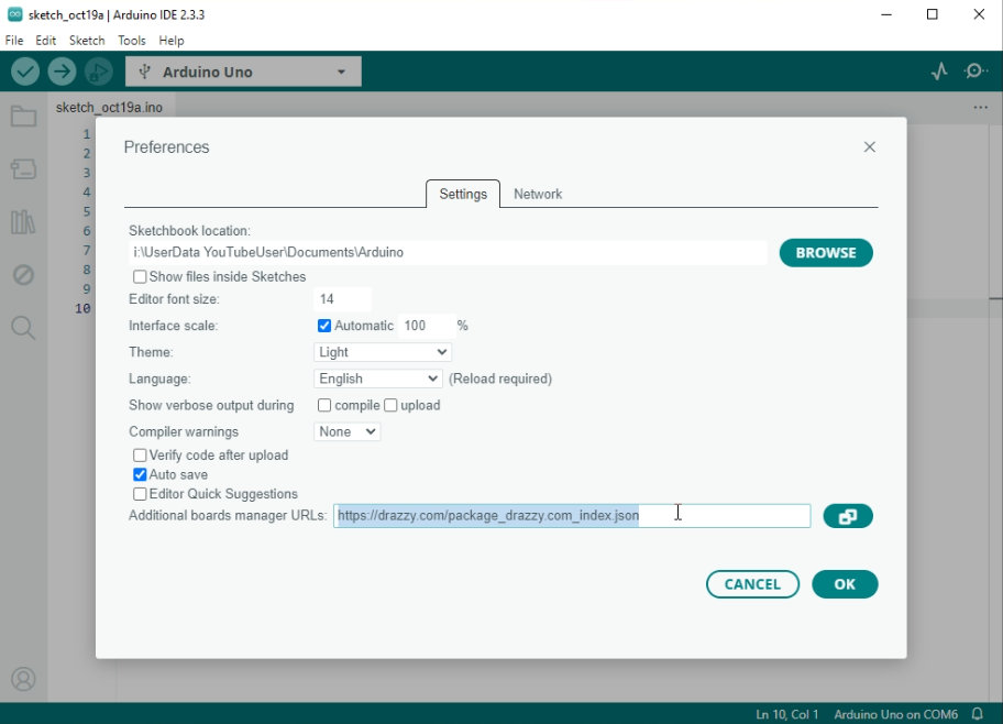
Then click the OK button, and open the menu Tools, go to Board: …… and click on Boards Manager… in the sub-menu that opens.
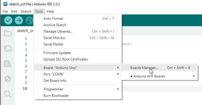
Then in the ‘toolbar’ that appears on the left, start typing ATTiny (at the top of the toolbar), and install the ATTinyCore (NOT the deprecated one!) as shown below.
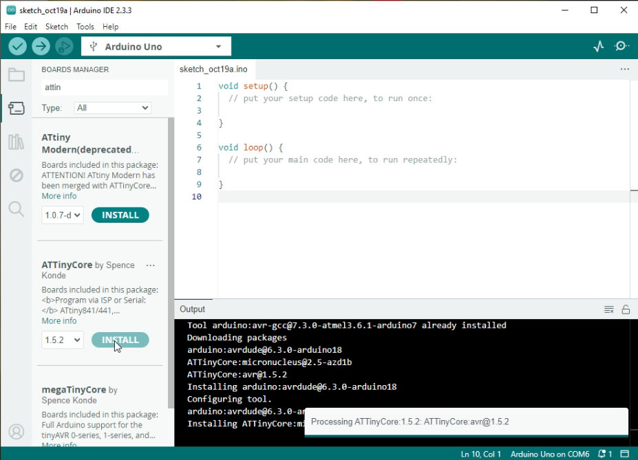
You (depending on what libraries and drivers you already have installed on your computer) will most likely get a whole bunch of questions if you would like to install drivers, install unsigned drivers (most likely with a red warning) etc etc. I just installed all of them to ensure a properly functioning (core) library. And after accepting them all you should see a status message like this one:

DISCLAIMER: Installing drivers and/or software from external sources are obviously at your own risk!
NOTE: The library version shown to you might of course be different than mine (especially if you’re installing it much later in the future after I published this article)
If you have received the Successfully installed Platform message, then this means that your Arduino IDE is now ready to start programming the ATtiny microcontrollers. If you do get an error of some sort, then please refer to the GitHub page of this library for support. I’m NOT the creator of the library, nor do I provide support for it. This article is just to explain in more simple terms how it works and to give a detailed explanation about the ATtiny microcontroller to be supplied with a couple of my published projects.
Programming your Arduino UNO (or other Arduino (compatible) board) as flasher (ISP)
To be able to flash the ATtiny microcontrollers we will actually need an external flasher. Luckily it’s very simple to turn your Arduino UNO into an flasher (ISP). Simply connect your Arduino UNO (or other compatible board) to your computer, select the correct board and port in the menu Tools.
Next open the menu File -> Examples -> 11.ArduinoISP -> ArduinoISP
NOTE: The number 11. might in be different for you/change in the future, but I’m guessing you get the point on where to go here😉
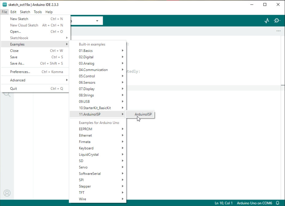
The Arduino IDE will now open a new sketch (most likely in a new window), you don’t need to change anything in this sketch if you’re using an Arduino UNO or one of my LABUNO (Overkill Edition) boards for example. If you are however using a 3.3V board like for example the Due or Zero, I would recommend to read the commented text in the sketch BEFORE proceeding!
Assuming you have already selected the correct board and port, you can proceed to click the upload sketch button (the round button with the arrow pointing to the right). After a few seconds you should now receive a message that the upload has completed.
Congratulations, you have now turned your Arduino UNO (or compatible) board into an ISP (In System Programmer) / ‘Flasher’.
Connecting the ATtiny to the Arduino UNO (to upload your sketch)
To upload your sketch to your ATtiny you will now need to hook up the ATtiny to your Arduino UNO (or compatible) board. First disconnect the UNO from the computer (just to be safe), and then connect the ATtiny to your Arduino UNO (or compatible) board as shown in the diagram below, I would recommend doing so on a (small) breadboard for example.

The 100nF ceramic capacitor at the ATtiny should be placed as close as possible to the ATtiny itself, with one leg connected to pin 8 of the ATtiny (VCC), and the other leg connected to pin 4 (GND) of the ATtiny (or directly to the ground rail/wire, whichever is closer!). This capacitor ensures stable operation of the ATtiny during programming.
The 10µF electrolytic capacitor shown next to the Arduino UNO should be connected to the reset pin (of the Arduino UNO) with it’s positive lead, and the negative lead should be connected to ground. This capacitor prevents the Arduino UNO from resetting while you are trying to upload the sketch to the ATtiny (via the Arduino UNO while using it as ISP).
NOTE: If you are using my XNL LABUNO Overkill Edition you don’t need to use the 10µF capacitor on the reset pin of the LABUNO. The board will simply not reset when uploading. And IF the LABUNO does reset (due to the Arduino IDE ‘commanding it’ to do so), then you can simply temporarily remove the RTS Reset jumper.
Connecting the ATtiny to the XNL LABUNO Overkill Edition with the ISP Speed Flash Board
If you however frequently have to flash smaller IC’s like the ATtiny, then you might want to check out my XNL LABUNO Overkill Edition and the XNL ISP Speed Flash Board. When using these two it will be even easier (and much faster) to flash the ATtiny25, 45, 85 and several other types of microcontrollers which are usually not supported by default by the Arduino IDE.
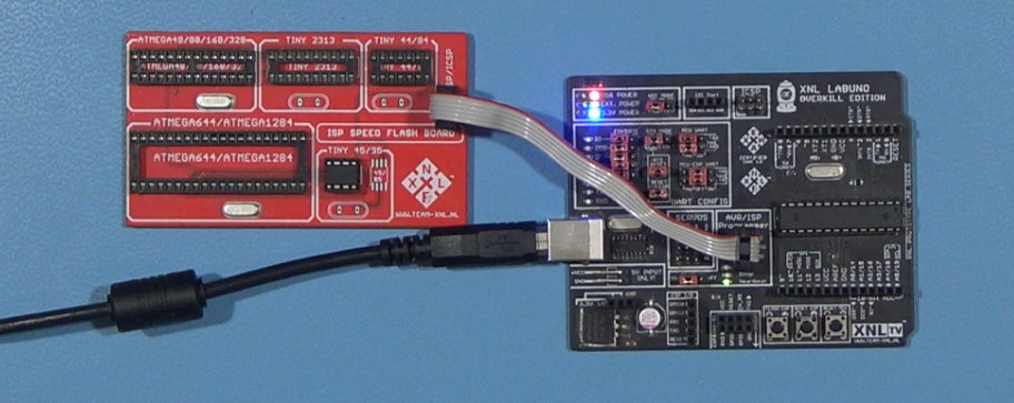
I won’t go too much into detail about these two boards (because that’s not what this article is about), but as you can see in the photo above: all it basically involves is connecting the XNL ISP Speed Flash Board to the LABUNO Overkill Edition, putting the ATtiny into the socket and you’re ready to flash it.
Configuring the Arduino IDE for your ATtiny
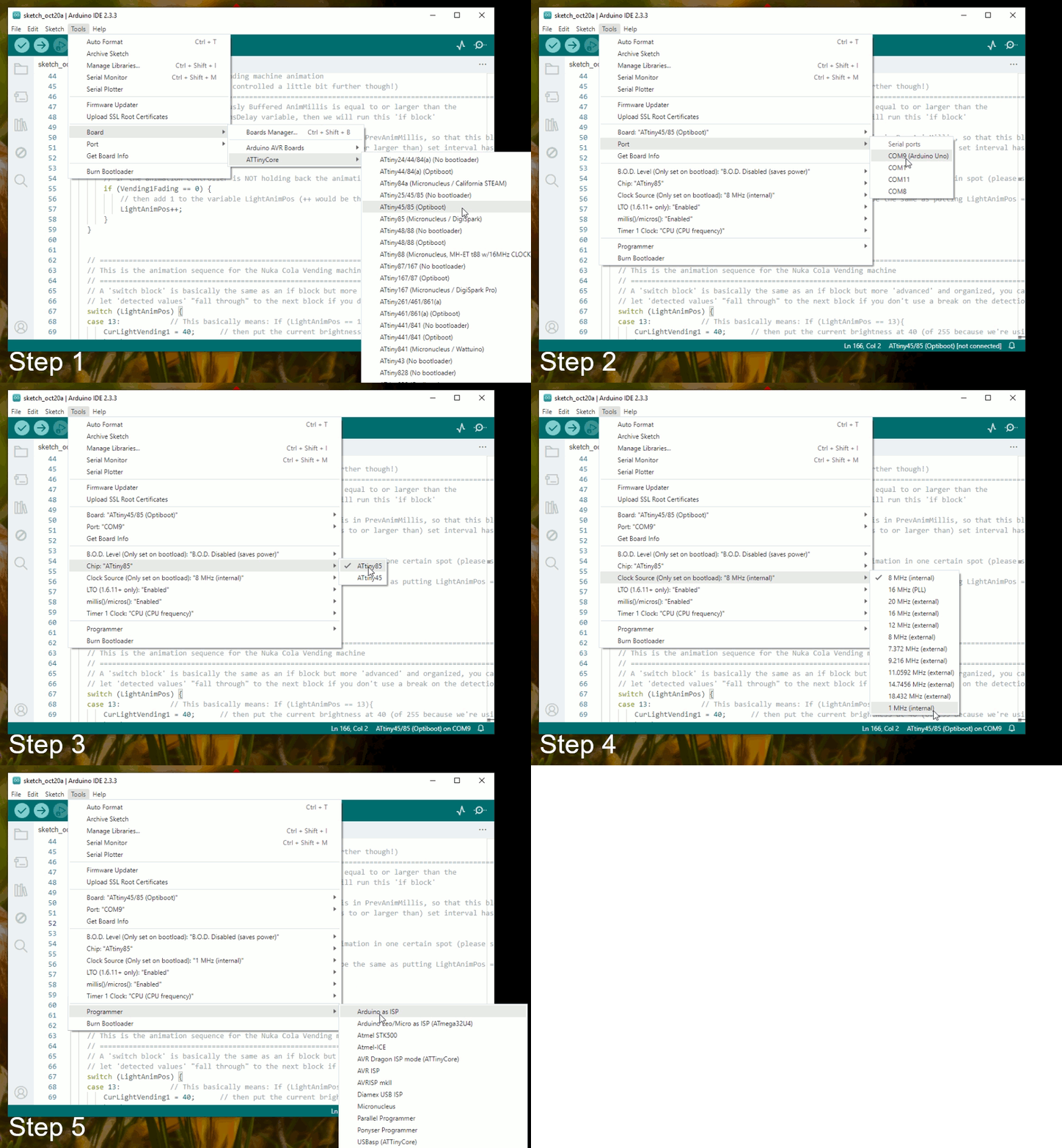
Now it’s time to configure the Arduino IDE to flash your ATtiny (while using the Arduino UNO (or compatible) board as flasher/ISP). To do so, perform the following steps (all in the menu Tools):
Step 1: Click On Tools -> Board -> ATTinyCore -> ATTiny45/85 (Optiboot) [see notes below]
Step 2: Click On Tools -> Port -> [Select the correct port for your Arduino UNO (or Compatible board)]
Step 3: Click On Tools -> Chip: …… -> ATtiny85 (Or the ATtiny45 if you’re using that one of course)
Step 4: Click On Tools -> Clock Source…. -> 1MHz (Internal) [see notes below]
Step 5: Click On Tools -> Programmer -> Arduino as ISP
I’ve also made an animated illustration below to demonstrate these steps (it cycles between the steps each 1800 milliseconds):
Some notes on the setting’s I’m using here
I’m using the Optiboot version/option because the No Bootloader option doesn’t seem to work on my clean installed Arduino IDE at all, it doesn’t even try to upload. However it’s no problem to use the Optiboot version in my opinion. And the speed I’m using in my configuration (1MHz) is the speed I usually use for my ATtiny projects. You can of course use a different speed for yours if required, but this might require some additional (software) ‘tweaks’ in your code to ensure correct functionality depending on what you set it to.
Also do note that if you are using an speed which says External, that you will need to connect a crystal oscillator (circuit) to pins 2 and 3 (XTAL1 & XTAL2). I however don’t recommend doing so unless absolutely necessary because you will obviously lose two I/O pins when doing so. Which is also why I didn’t cover using an external oscillator for the ATtiny in this article.
Flashing your sketch to your ATtiny
And now you’ve completely setup your ATtiny and the Arduino IDE to start uploading your code/firmware/sketch to your ATtiny. Do however note that you CAN NOT just click on the ‘round upload button with the arrow‘ to upload your sketch to your ATtiny! If you try to do so, you will most likely be ‘waiting forever’ with the ‘Uploading’ status popup showing, or you will eventually get an error that it can’t upload the sketch.
Instead you will have to upload your sketch to the ATtiny by clicking on: Sketch -> Upload Using Programmer as shown below.
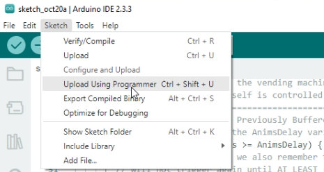
If everything went well, your code/firmware/sketch should now be uploaded and be running on your ATtiny😊

Final Words & Other Microcontrollers Recommendation
I hope that this article / tutorial has proven to be useful to you and that it has helped you setup and understand the ATtiny a bit more😊, if so then please consider Subscribing to my YouTube channel, not only to help me grow the channel and thus being able to make more of these projects and articles, but also to make sure that you won’t miss out on possible interesting projects and topics in the future😊.
Lastly I would also like to recommend you to have a look at some of the other ATtiny microcontrollers (by Googling them) like the ATtiny2313, the ATtiny44 and ATtiny84 which have a bit more capabilities than the ATtiny25/45/85 but are often still quite a bit more suitable for smaller projects than for example the most commonly used ATMega328 😊.
Have fun with your Tiny Projects😉, and hopefully until next time😊


